
How to Restore ICOM Next with All LEDs Red and System LED Blink Red/Yellow


Problem with BMW ICOM Next: did an update on my motorcycle and everything went fine and today when I connect icom to OBD – all leds are just on with red color, system one is blinking red/yellow.

Please do exactly as follow:

1. Disconnect the ICOM Next device from the power supply or vehicle.
2. Go to the directory

C:\ProgramData\BMW\ISPI\data\TRIC\ICOMNext\ICOM-Image-xx-yy-zz.
Note: This directory is hidden. Please see [?00045002EN].
2.1. Copy the file ICOM_Next-rootfs-xxxxxx.tar.gz to the root directory of the USB flash drive.
2.2. Copy the file ICOM_Next-app-yyyyyy.tar.gz to the root directory of the USB flash drive.

Note:
– An ICOM_Restore.bin file is not available. Please use the files from the ICOM Next firmware package as described above.
– xxxxxx and yyyyyy in the file names represent the version numbers of the respective files.
– If the directory contains more than one ICOM-Image-xx-yy-zz folder, please choose the most recent one, i.e. the folder with highest number. The ICOM Next will then be ready to use without further updates.
– It is important that the files are copied to the root directory of the USB flash drive.

3. Connect the USB stick to the BMW Diagnostic Tool ICOM Next.
4. Press and hold the button located on the right-hand side of the ICOM Next, next to the OBD II cable connection socket.
5. Continue to hold the button, connect the device to the vehicle’s OBD II jack and keep the button pressed until the LEDs on the ICOM Next glow red.
6. Release the button and within five seconds, push the button three times. This starts the firmware update.
Note: The update may take several minutes. Do not disconnect the ICOM Next as long as any LED glows red.
7. When all LEDs on the ICOM Next have stopped glowing, the Emergency Firmware Update is complete. You can now disconnect the USB flash drive.
8. IMPORTANT: When the Emergency Firmware Update is finished, the ICOM Next must be connected to your network with a LAN cable in order to be reconfigured since all previous settings have been lost. If there is a “user.settings” file on the USB flash drive, it will be installed after the firmware update.

The RIGHT reset button on Original ICOM Next the button behind the tiny black hole! (in red circle).
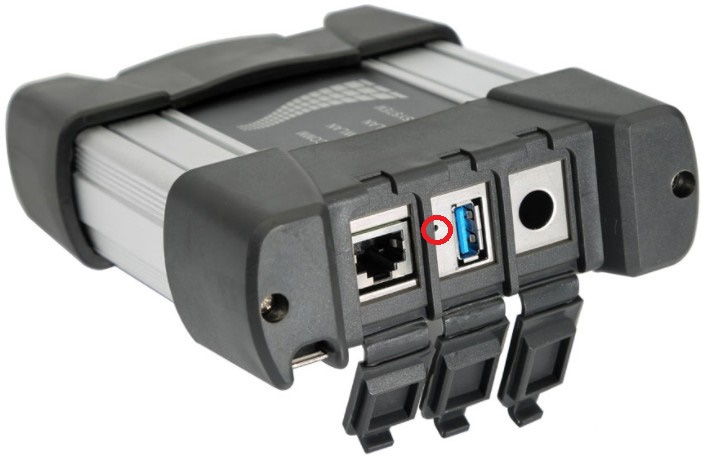
Icom-Next-Reset-Button-1

WARNING!

Not Orig ICOM NEXT has another reset button!!!!
The red circle is a NON OEM ICOM NEXT reset button, and the blue is the OEM ICOM NEXT reset button!!!!!
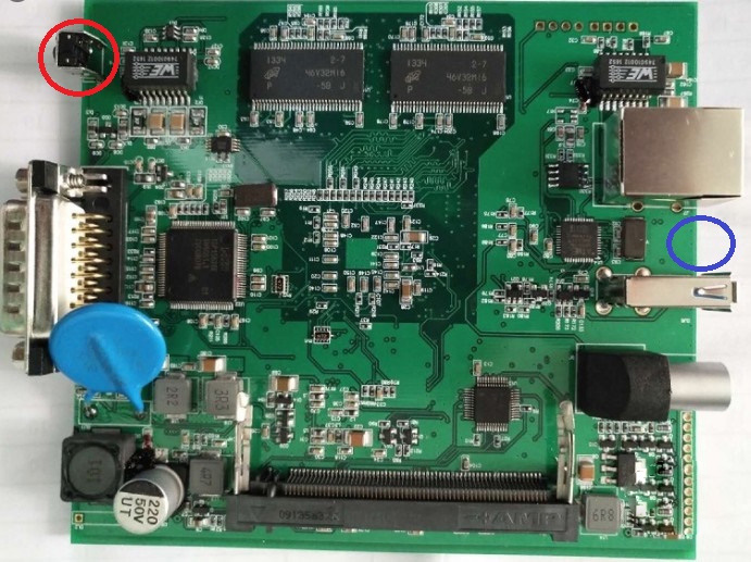
Icom-Next-Reset-Button-2

And there is one original ICOM NEXT PCB where a reset button in the blue circle! (NOT THE RED!!!)
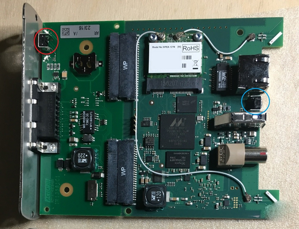
Icom-Next-Reset-Button-3

Question: what icom_restore.bin is doing?

Answer: The existing restore.bin is for ICOM A or A2!

And here is one user’s success feedback: Yesterday out of a blue my ICOM Next OEM has stopped to work, ethernet can’t find IP address. In about 2 minutes ICOM was recovered and connected to the ethernet network. PS: He follow the above ICOM Next store procedure.

Comments

Popular posts from this blog

How to setup BMW ISTA/P Loader for ICOM A2 ENET cable K+DCAN adapter

The text here, as a user manual of BMW ISTA/P Loader / ICOM Emulator,  is aimed to help those puzzled with ISTA/P Loader setup for  ICOM A2 , ENET cable, K+DCAN  USB interface. Note: all info here not original, shared by a forum member So try at your own risk! Main content: Part 1 – Compatible device Part 2 – Latest ISTA/P Loader update information Part 3 – How to install ISTA/P Loader v4.x Part 4 – How to use  ISTA/P loader with ICOM A2, K+DCAN cable, ENET cable Part 5 – How to shut down ISTA/P Part 1 – Compatible device: ISTA/P Loader compatible with ICOM A2 (OEM or clone), K+DCAN USB and ENET   Part 2 – Latest ISTA/P Loader update information: NEWEST – ISTA/P Loader V4.8  update info: Free download BMW ISTA-P Loader V4.8.7 to get all new info yourself …… ISTA/P Loader V4.2 update info: Custom resolution option added Improved detection of bmw scan tool ISTA-P install location. Improved compatibility with windows 10 Code...

JOHN DEERE DIAGNOSTIC OPTIONS

JOHN DEERE DIAGNOSTICS John Deere has recently been in the news because of their strict opposition to allowing farmers, equipment owners, and repair shops access to the information they need to repair and maintain their vehicles. If you read the main stream news, you would be left to believe that John Deere diagnostic with a computer is impossible. Well, we are here to help dispel that myth and give some more exposure to some tools that actually do perform diagnostics on John Deere. There are actually several solutions in the market, some of which we will cover in this post. JOHN DEERE EDL AND SERVICE ADVISOR The very best solution in the market is what the dealers use. John Deere dealers use a combination of PC-based computer with two critical components – John Deere Service Advisor software and the John Deere EDL v3 Adapter . The EDL v3 adapter looks like the picture shown below. It comes with a hard carry case, the adapter itself, a 9-pin connector, and the USB ca...

Hyundai Automatic Transaxle-No Movement in Drive or Reverse Gear Repair

If you are servicing a vehicle with no movement in drive or reverse gear, follow the procedure shown below.And for more Hyundai projects,please check here:Hyundai Repair Cases REPAIR PROCEDURE: 1.Check for DTC in both the “Engine” and “Automatic Transaxle” menus: *   If DTC are found,you need repair it firstly. *   If no DTC are found, go to Step 2. 2.Remove the dipstick and check the ATF for a strong burnt smell. If the smell does not provide conclusive results, remove the oil pan and check for metal particles in the pan: *   If a strong burnt smell or metal particles are found, replace the transaxle *   If not, go to Step 3 NOTE: ATF that is a dark brown or black color does not indicate an internal transaxle concern;do not replace the transaxle. SPIII may change color to a dark brown after 10,000 to 25,000 miles in service. This change is normal for this type of ATF. VERIFY THE RANGE SWITCH ADJUSTMENT: 3.Move the shift lever to ...