JOHN DEERE DIAGNOSTICS
John Deere has recently been in the news because of their strict opposition to allowing farmers, equipment owners, and repair shops access to the information they need to repair and maintain their vehicles. If you read the main stream news, you would be left to believe that John Deere diagnostic with a computer is impossible. Well, we are here to help dispel that myth and give some more exposure to some tools that actually do perform diagnostics on John Deere. There are actually several solutions in the market, some of which we will cover in this post.
JOHN DEERE EDL AND SERVICE ADVISOR
The very best solution in the market is what the dealers use. John Deere dealers use a combination of PC-based computer with two critical components – John Deere Service Advisor software and the John Deere EDL v3 Adapter. The EDL v3 adapter looks like the picture shown below. It comes with a hard carry case, the adapter itself, a 9-pin connector, and the USB cable. This tool is available for purchase from our website obd2tool.com as well.
The John Deere EDL Adapter also has a variety of “extra” cables you can purchase, almost all of which are for some of the much older equipment. You can see all of the available cables on our website.
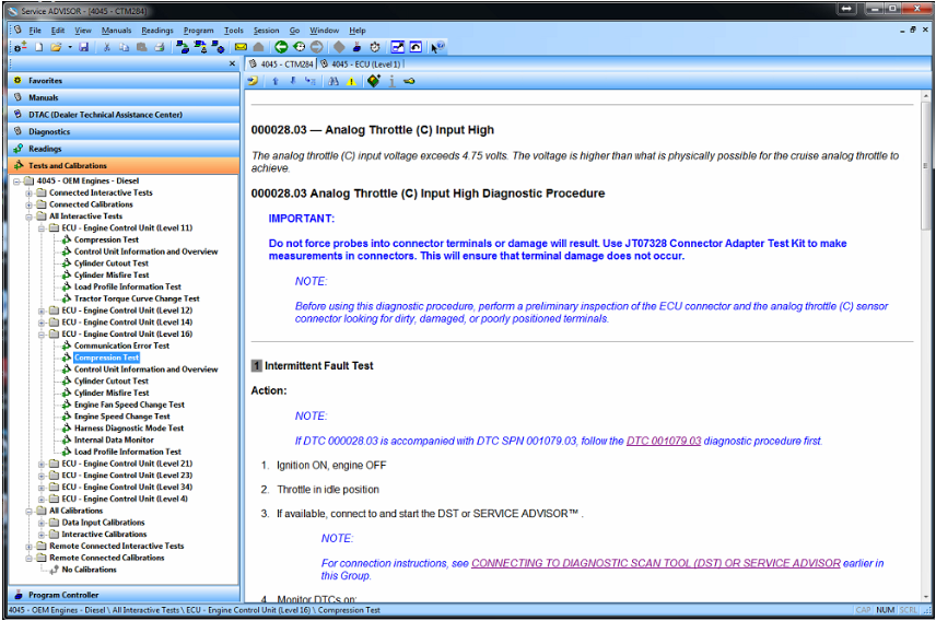
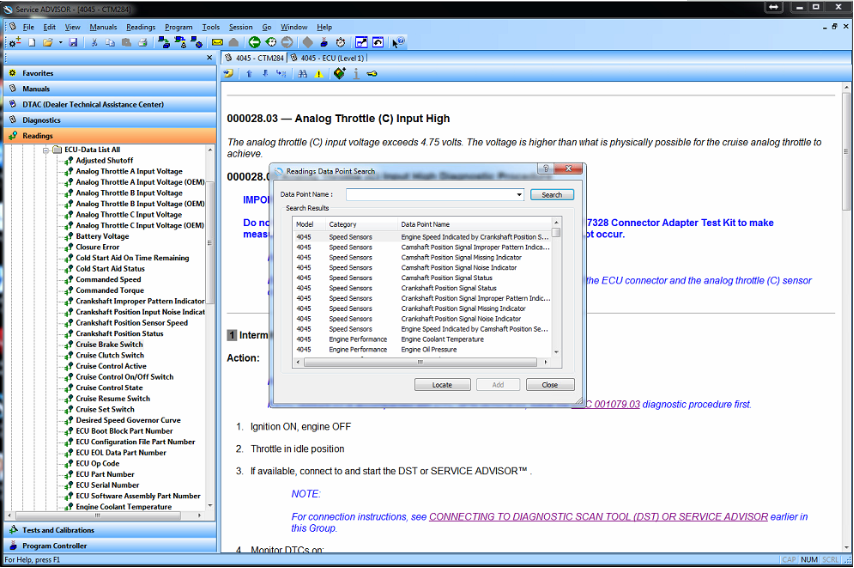
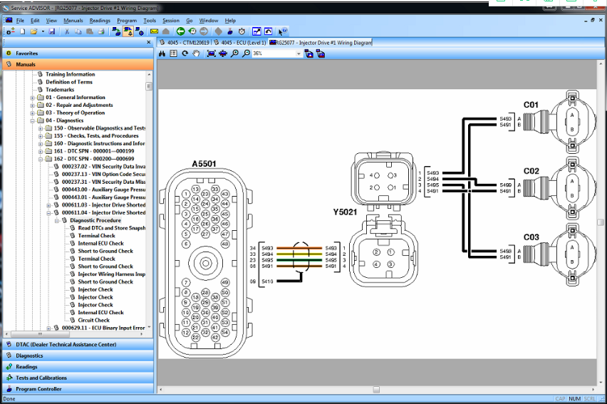
The problem comes into the other side of the equation — The diagnostic software. John Deere dealers refuse to sell this software to anyone. This includes owners of the equipment, repair shops, or anyone else for the matter. The reason for this is simple: Dealers don’t want anyone besides themselves to perform John Deere diagnostic tests and commands, since it would in sense be money leaving their own pockets. If there is no one else that has the software solutions to perform the advanced diagnostics, the customer has to go to them. However, we were fortunate enough to have the opportunity to get our hands on this software, so here are some screen shots showing what this software looks like.
John Deere has recently been in the news because of their strict opposition to allowing farmers, equipment owners, and repair shops access to the information they need to repair and maintain their vehicles. If you read the main stream news, you would be left to believe that John Deere diagnostic with a computer is impossible. Well, we are here to help dispel that myth and give some more exposure to some tools that actually do perform diagnostics on John Deere. There are actually several solutions in the market, some of which we will cover in this post.
JOHN DEERE EDL AND SERVICE ADVISOR
The very best solution in the market is what the dealers use. John Deere dealers use a combination of PC-based computer with two critical components – John Deere Service Advisor software and the John Deere EDL v3 Adapter. The EDL v3 adapter looks like the picture shown below. It comes with a hard carry case, the adapter itself, a 9-pin connector, and the USB cable. This tool is available for purchase from our website obd2tool.com as well.
The John Deere EDL Adapter also has a variety of “extra” cables you can purchase, almost all of which are for some of the much older equipment. You can see all of the available cables on our website.
The problem comes into the other side of the equation — The diagnostic software. John Deere dealers refuse to sell this software to anyone. This includes owners of the equipment, repair shops, or anyone else for the matter. The reason for this is simple: Dealers don’t want anyone besides themselves to perform John Deere diagnostic tests and commands, since it would in sense be money leaving their own pockets. If there is no one else that has the software solutions to perform the advanced diagnostics, the customer has to go to them. However, we were fortunate enough to have the opportunity to get our hands on this software, so here are some screen shots showing what this software looks like.
Comments
Post a Comment