
BMW ICOM NEXT A


BMW-ICOM-NEXT-A

The ICOM Next A is a multifunctional vehicle interface that is designed to be used in workshops worldwide. It has been specially developed for use by workshop and service personnel in support of service consulting, diagnosis, and vehicle programming processes.

The philosophy behind the ICOM Next A is to provide universal deployment capabilities irrespective of the vehicle type and communication interface. To this end, the interface unit is distributed over several components. Each individual module is designed to be used in different combinations for special tasks.

The ICOM NEXT system comprises the following components: diagnostic unit incl. OBD cable, MOST diagnosis adapter, legacy vehicle adapter, and motorcycle adapter. An overview of all the devices is shown in the table below.

OPERATING AND STORAGE CONDITIONS

Electric operation:
Supply voltage KL30: 8V to 18V
Max. power consumption: 1.5 A (incl. MOST diagnosis adapter)
Ambient conditions during operation:
Ambient temperature range: 0 °C to +45 °C
Relative humidity at max. 25 °C: 10% to 80%, non-condensing
Temperature gradient: 5 °C/h
Ambient conditions for storage:
Ambient temperature range: -20 °C to +60 °C
Relative humidity at max. 25 °C: 10% to 80%, non-condensing
Temperature gradient: 5 °C/h

FUNCTION
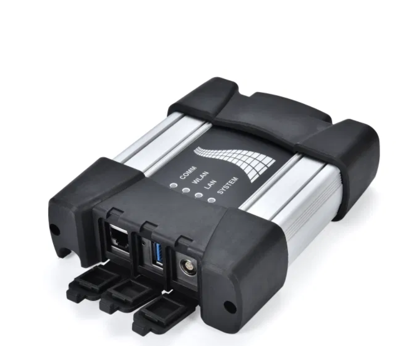
The ICOM NEXT A is the base component. Physically, it provides the interfaces for linking up to the vehicle’s OBD diagnostic interface together with the interfaces for adaptive integration in the workshop’s network. With its powerful computer kernel, it serves as a protocol converter and takes over the exchange of data between the tester and the vehicle’s control devices, as well as processing the signals to the connection for the measuring device. The ICOM NEXT A is supplied with power from the vehicle’s on-board electrical circuit (terminal 30) via the OBD connection.

In electric operation, the BMW Diagnostic Tool ICOM NEXT A is specified for a minimum voltage of 8V.
The unit will only function reliably if the supply voltage does not fall below this minimum level.

Comments

Popular posts from this blog

How to setup BMW ISTA/P Loader for ICOM A2 ENET cable K+DCAN adapter

The text here, as a user manual of BMW ISTA/P Loader / ICOM Emulator,  is aimed to help those puzzled with ISTA/P Loader setup for  ICOM A2 , ENET cable, K+DCAN  USB interface. Note: all info here not original, shared by a forum member So try at your own risk! Main content: Part 1 – Compatible device Part 2 – Latest ISTA/P Loader update information Part 3 – How to install ISTA/P Loader v4.x Part 4 – How to use  ISTA/P loader with ICOM A2, K+DCAN cable, ENET cable Part 5 – How to shut down ISTA/P Part 1 – Compatible device: ISTA/P Loader compatible with ICOM A2 (OEM or clone), K+DCAN USB and ENET   Part 2 – Latest ISTA/P Loader update information: NEWEST – ISTA/P Loader V4.8  update info: Free download BMW ISTA-P Loader V4.8.7 to get all new info yourself …… ISTA/P Loader V4.2 update info: Custom resolution option added Improved detection of bmw scan tool ISTA-P install location. Improved compatibility with windows 10 Code...

PIWIS Tester Technical Information

WF51 – Re-coding Instrument Cluster (Workshop Campaign) Important: CRITICAL WARNING – This campaign includes steps where control unit(s) in the vehicle will be programmed with the PIWIS Tester. The vehicle voltage must be maintained between 13.5 volts and 14.5 volts during this programming. Failure to maintain this voltage could result in damaged control unit(s). Damage caused by inadequate voltage during programming is not a warrantable defect. The technician must verify the actual vehicle voltage in the PIWIS Tester before starting the campaign and also document the actual voltage on the repair order. Please refer to Equipment Information EQ1401 for a list of suitable battery chargers/power supplies which should be used to maintain vehicle voltage. Model Year: 2015 Vehicle Type: Cayenne S E-Hybrid (92A) Concerns: Instrument cluster Information: The instrument cluster on the affected vehiclesmay have been coded using an incorrect coding rule. As a result, there...

How to flash using a DoIP hardware

  This is an Article showing just how simple it is to flash in DTS Monaco , over DoIP (Diagnostic over Internet Protocol). These newer units can ONLY be flashed over DoIP. Trying to flash them via CAN, will very likely brick your control unit, so that should not be attempted, under any circumstances! A DoIP hardware is required to flash these newer units. Such a hardware can be an SDConnect C4 DoIP , ECOM or VCX SE . DoIP brings signifficant advantage versus CAN, by that it is much faster (eg. flashing times take a few minutes, instead of several hours, telematics disks are not needed anymore, etc etc). Once you own the equipment, it will need to be correctly set up. There are online guides available, that show how to set up these devices. Following is the DTS Monaco guide on how to flash using a DoIP hardware! First, we’ll need to select the relevant SMR-D file, of the control unit, which we’ll be interacting with. Once interfacing with the control unit, before flash...